SIM RACING - full mouse control and vehicle dynamics

other games? SCROLL down or CLICK here!


SLOW INTERNET WARNING: THERE ARE PICTURES!


BEAMNG FULL MOUSE STEERING, THROTTLE AND (TRAIL)BRAKING TUTORIAL:

NOTE: beamNG supports binding mouse input to pedals, as well as steering WITHOUT third party applications!

1. MENU > OPTIONS > GAMEPLAY:

  • ABS MODE = REALISTIC ABS ONLY
  • DEFAULT GEARBOX BEHAVIOUR = REALISTIC
  • GEARBOX SAFETY ASSISTANT = OFF
  • CLUTCH ASSISTANT (MANUAL TRANSMISSION) = ON (!1)
  • THROTTLE ASSISTANT (MANUAL TRANSMISSION) = ON (!1)
  • OVERSTEER REDUCTION ASSISTANT = OFF
    UNDERSTEER REDUCTION ASSISTANT = OFF
  • SLOWER STEERING AT HIGH SPEED = OFF
  • LIMIT STEERING AT HIGH SPEED = OFF

  • DEFAULT IGNITION STATE = OFF (optional)
  • START VEHICLE ENGINES PREHEATED = OFF (optional)
  • START RACE BRAKES PREHEATED = OFF (optional)
(!1) - disable if you are driving automatic or DCT drivetrains

2. MENU > CONTROLS > BINDINGS > VEHICLE:

NOTE: unbind WASD and/or arrows!

3. CHOOSE YOUR Y-AXIS METHOD (CLICK):

COMBINED (EASY)

SIMPLIFIED MOUSE HANDLING SETUP FOR NEWBIES:


COMBINED THROTTLE&BRAKE = VERTICAL Y MOUSE AXIS:

  • …
    • i.e. to bind, move the mouse up & down
  • FILTER = WHEEL (DIRECT)
  • INVERTED AXIS = ON
  • LINEARITY = 1
  • DEADZONE (REST) = 0
  • DEADZONE (END) = 0.5
    • use DEADZONE (END) to change the input sensitivity (borders/limits)


STEERING (AXIS/MOUSE) = HORISONTAL X MOUSE AXIS:

  • …
    • i.e. to bind, move the mouse left & right
  • FILTER = WHEEL (DIRECT)
  • 1:1 STEERING ANGLE = 0 (!1)
  • INVERTED AXIS = OFF
  • LINEARITY = 1
  • DEADZONE (REST) = 0
  • DEADZONE (END) = 0
    • use DEADZONE (END) to change the steering sensitivity (borders/limits)


(!1) - visual only. sets the interior steering wheel steering ratio

…

SEPARATE (HARD)

MOUSE TRAILBRAKING SETUP WITH OVERLAPPING AXES:


THROTTLE = VERTICAL Y MOUSE AXIS:

  • …
    • i.e. to bind, move the mouse up & down
  • FILTER = WHEEL (DIRECT)
  • INVERTED AXIS = ON
  • LINEARITY = 1
  • DEADZONE (REST) = 0.5
  • DEADZONE (END) = 0.375
    • use DEADZONE (REST) & (END) to change the throttle sensitivity (borders/limits)


BRAKE = VERTICAL Y MOUSE AXIS:

  • …
    • i.e. to bind, move the mouse up & down
  • FILTER = WHEEL (DIRECT)
  • INVERTED AXIS = OFF
    • (UNLESS using a ball mouse)
  • LINEARITY = 0.75
  • DEADZONE (REST) = 0.45
    • (LOWER = trailbrake start, smooth; HIGHER = trailbrake end, rough)
  • DEADZONE (END) = 0.25
    • (LOWER = less pressure, smooth; HIGHER = more pressure, rough)


STEERING (AXIS/MOUSE) = HORISONTAL X MOUSE AXIS:

  • …
    • i.e. to bind, move the mouse left & right
  • FILTER = WHEEL (DIRECT)
  • 1:1 STEERING ANGLE = 0 (!1)
  • INVERTED AXIS = OFF
  • LINEARITY = 1
  • DEADZONE (REST) = 0
  • DEADZONE (END) = 0
    • use DEADZONE (REST) & (END) to change the steering sensitivity (borders/limits)


CLUTCH = LEFT SHIFT:

  • FILTER = KEY (SMOOTH) (!2)
    • (also try static and dynamic bind modifiers)

PARKING BRAKE (HOLD) = SPACEBAR

  • FILTER = KEY (SMOOTH) (!2)
    • (also try static and dynamic bind modifiers)

(!1) - visual only. sets the interior steering wheel steering ratio
(!2) - smoothens binary input (0 AND 1 becomes 0.0 to 1.0)

…


NOTE: to aid with mouse sensitivity and/or coordination, use UI APPS > ADD APP > PEDALS AND AXIS to see your current input values. i recommend placing it roughly in the middle of the screen as a “crosshair”. alternatively, RELATIVE (behind) and CHASE camera modes can also help (bound to keys 5 and 6 by default)

#fuckai

<3

1 Like

Think you could do a forum tutorial on how to actually drift, not “drift” like sean boswell in the beginning of tokyo drift. I always end up in a ditch, a wall, or spinning out. Or atleast a way to practice

1 Like
THIS WORKS WITH ANY GAME: richard burns rally (RSF), dirt rally, ea sports wrc, assetto corsa rally, iracing, ride, rfactor, forza horison, gran turismo, project cars, raceroom racing experience, carx drift racing, automibilista, farming simulator, ea sports f1, trackmania, need for speed, ridge racer, midnight club, genki racing project, tokyo xtreme racer, wipeout, ballisticng, mario kart, test drive, bus driver simulator, my summer car, my winter car, snowrunner, mudrunner, wreckfest, ms flight simulator, VATSIM, x-plane, dcs world, war thunder, euro truck simulator, grand theft auto, and BLAH BLAH BLAH… YOU’RE WINNER!!!

COLLECTION OF VIRTUAL JOYSTICKS (GAMEPADS) AND STEERING WHEELS (EMULATORS), INPUT REMAPPERS, INPUT FEEDERS & BUS (DEVICE) DRIVERS:

…like a virtual (on-screen) keyboard that your phone has! except this one is a “mouse controlled” joystick/gamepad, see?

SLOW INTERNET WARNING: THERE ARE PICTURES!


THE NEW METHOD (no vJoy):

virtual joystick appears as a HID device in WIN+R > joy.cpl… which i am controlling with a mouse! EPIC SWAG MLG 420 STYLE!!!1

YOU NEED 2 THINGS:

MouseSteering (Github) - the interface

+

ViGEmBus (Github) - the driver

it turns your mouse into a joystick, i.e. the relative position of your cursor from the centre of the screen, which makes it easy to bind each quarter (or half) of the screen +X/-X and +Y/-Y to anything in any game!

MORE ABOUT MouseSteering (CLICK)
  • MouseSteering comes in a .zip portable archive (no installation)
  • MouseSteering does NOT require vJoy installed!
  • MouseSteering is NOT to be confused with MouseSteering_V1.7.2 (Steam Discussions)
  • MouseSteering supports X/Y/Z axes, i.e. XInput analogue buttons 6/7
  • MouseSteering has a customizable text (.toml) config
  • MouseSteering can toggle any axis on demand (boundable keys)

TIP1: set snap_input = false in config.toml for unfiltered linear movement
TIP2: set edge_scaling = true under [throttle_config] for more sensitive pedals (technically edge_scaling option is the deadzone)

…

MORE ABOUT ViGEmBus (CLICK)
  • ViGEmBus is a digitally signed kernel-mode 32/64 bit open source device (bus) driver
  • ViGEmBus can be uninstalled via WIN+R > appwiz.cpl
  • ViGEmBus is deprecated (archived), but still works on Win7 up to Win11! ^_^
  • ViGEmBus is a fork of vXbox, also known as ScpVBus
  • ViGEmBus’s virtual joystick device (XBOX 360 Controller) shows up ONLY when in use by a feeder, e.g. MouseSteering. emulation of other controllers is dependant on the feeder (which device is it coded to emulate)
  • unlike vJoy, ViGEmBus does NOT have an interface

NOTE: for more information, visit this official page

…


THE OLD METHOD (using vJoy):

LEGACY vJoy INSTRUCTIONS (CLICK)

YOU NEED 2 THINGS:

Virtual Controller (SourceForge) - the interface

+

vJoy v2.1.9.1 (Github / SourceForge) - the driver

it translates (feeds) configurable inputs (position, buttons) of your mouse to vJoy, emulating a joystick, which makes it easy to bind each quarter (or half) of the screen +X/-X and +Y/-Y to anything in any game!


OTHER vJoy VERSIONS (CLICK)

…

PSA1: Virtual Controller (interface) may NOT work on Win11!
PSA2: NEWER versions of vJoy did NOT work for me on Win10 (winutil) @ march 2025. GET v2.1.9.1 INSTEAD!!!

MORE ABOUT vJoy (CLICK)
  • vJoy is a digitally signed kernel-mode 32/64 bit open source device (bus) driver
  • vJoy can be uninstalled via WIN+R > appwiz.cpl or C:\Program Files\vJoy\unins000.exe
  • NOTE: on laptops, vJoy may disable itself to conserve battery. disable this via Device Manager > Human Interface Devices > vJoy Device > Energy Management
  • vJoy supports vXbox (Github), vKeyboard (Github) and vMouse (Github)!

…

MORE ABOUT Virtual Controller (CLICK)
  • do NOT close Virtual Controller during the game (minimise instead)
  • Virtual Controller can be uninstalled via WIN+R > appwiz.cpl or C:\Program Files\Virtual Controller\unins000.exe
  • NOTE: i have a “tutorial” for it a few lines down below!

…


alternatives are provided down below. check them all out! ^_^

…


ALTERNATIVE/OTHER MODERN/NEWER REMAPPERS/FEEDERS/VIRTUAL DEVICES:

including the penguins (tuxes)! <3
LIST OF VIRTUAL JOYSTICKS & INPUT REMAPPERS (CLICK)

MouseSteering_V1.7.2 (Steam Discussions)

NOTE: the original source code is from 2015, but there is a newer (2021) fork of it on Github

  • windows only (but AHK supports linux)!
  • a popular autohotkey (AHK) script for mouse steering that only has a horizontal X axis
  • uses RawInput (no interpolation/smoothing)
  • notably, has a mouse “force feedback” in the form of a “push back”, return-to-centre
  • has toggleable key binds for the input/steering telemetry (on-screen values)
  • TRIVIA: iirc was first scripted for assetto corsa, but then was forked and further developed for dirt rally games. works with ANY game, just like everything else listed here!

(hidden: author advertises ai slop)

x360ce (also on Github)


AntiMicroX (Github)

  • supports linux. x11 AND wayland
  • supports mouse and keyboard
  • TIP: unless remapping a PHYSICAL joystick, use a VIRTUAL one!

InputPlumber (Github)

  • linux only
  • uses evdev
  • rust btw

Xremap (Github)

  • linux only. x11 AND wayland
  • uses evdev AND uinput
  • supports mouse and keyboard

Input Remapper (Github)

  • linux only. x11 AND wayland
  • supports mouse and keyboard

QJoyPad (Github)

  • linux x11 only
  • supports mouse and keyboard
  • the oldest anarchy remapper (that still works)

UCR - Universal Control Remapper (Github) - C# version


UCR - Universal Control Remapper (Github) - AHK version

  • windows only
  • supports mouse
  • possible to change absolute AND relative input modes for mouse deltas!

Mouse2Joystick (Github)

  • windows only
  • requires ViGEmBus (Github)!
  • changes X/Y coordinates only on CONSTANT cursor movement (absolute input mode)
  • movement is limited by the boundaries of the monitor resolution!

mouse2joystick (Github)

  • linux only
  • bootstrapping script
  • steering is hardcoded to be used only with held mouse buttons

MTVJ - MouseToVJoy (itchio)

  • windows only
  • requires vJoy!
  • mouse steering works, but throttle and brake is bound to the mouse button (?)
  • has separate clutch & handbrake axes. shifting is bound to scroll wheel (?)

msfs_mouse_yoke (Github)

  • a windows only python script
  • uses X/Y/THROTTLE axes (bound to mouse wheel)
  • for flight simulators only (?)

KeyboardSplitterXbox (Github)

  • windows only
  • treats every connected HID keyboard as a separate device (otherwise windows will receive inputs all the same; common problem)

Joystick Gremlin (Github)


vJoySerialFeeder (Github)

  • windows only
  • requires vJoy!
  • for nerds only
  • uses uinput on linux

map2 (Github)

  • for linux nerds only
  • python config

FreePIE (Github)

  • for windblows nerds only
  • python config

NOTE1: you may also want a device driver to have something to remap - xpadneo (Github) or even Steam Input Configurator (archwiki)

NOTE2: as with any remapper/feeder, it is possible to remap a physically connected joystick/gamepad (even a steam deck)!

…


OLD vJoy + Virtual Controller TUTORIAL:

which i have made years ago (ancient ■■■■)…
VirtualController.exe TUTORIAL (CLICK)
  1. install vJoy
    (you may have to restart)

  2. install virtual controller
    (can be any feeder of choice - the list is above)

  3. in Start open / search Configure vJoy
    (C:\Program Files\vJoy\x64\vJoyConf.exe)

  4. configure like so:


  5. (axis may differ depending on your vJoy version).
    plural of axis is axes, however, for searchability sake,
    i will omit this easily confusing word.

  6. close vJoyConf
    (there can only be one (1) vJoy interface active)

  7. in Start open / search Virtual Controller
    (C:\Program Files\Virtual Controller\VirtualController.exe)
    (next steps may differ depending on your feeder application,
    but essentially they are all the same -
    the goal is to bind / remap mouse XYZ input to vJoy XYZ input)

  8. Settings > IO Devices > Setup > Mouse.
    with this feeder, we will be using the LLHook API (“low level” hook) to feed mouse inputs. this is because other API, such as RawInput will not be able to “lock” the mouse INSIDE the screen edges / bounds (of the window or screen’s native resolution) (not to be confused with the “lock” features in this window), because, as mentioned in the optional trivia, it is a relative input mode, so it sends input data to vJoy infinitely, exceeding the maximum value range. once again, a joystick is both a relative and absolute input device, and the XYZ axis is referring to thumbsticks AND/OR triggers of a joystick (they differ model to model), which usually are relative, however, in this case they are, in fact, absolute, unless you have changed their input mode, so the mouse has no virtual boundaries because it is also a relative device of input. if the joystick always has physical boundaries and limitations to how far it is allowed to go, mouse does not.
    anyway, unfortunately, i have yet to find a better solution on how to make this better, because using the LLHook API (in this particular feeder) comes at a cost - it is NOT CALIBRATED (unless it is not, but make sure!) !!! this basically means that: 1. IT DOES NOT RESPECT NEUTRAL POSITION (centre of the screen), to be precise, it is not directly in the middle of the screen, instead it has “drifted” away to some side. high level API, like XInput, could be better for this matter, but this feeder does not have it. feel free to try another! 2. it may overflow negative or positive value range (below 0 or over 16384 / 32768 / 65536, e.g. -100% or 200%) - example photo of this situation provided below. in this case it would be easier to somehow limit vJoy’s maximum value range, but i think it is impossible without compiling your own vJoy via its SDK and you will be left with an unsigned driver. EDIT: wrong! it would be futile. the value range exceeding problem has to do with input being relative (explained somewhere in this post). if your feeder has an absolute mode for mouse input - use it. nevertheless, luckily, joy.cpl has a calibrate feature, read down below. 3. moreover, you may have noticed there is no XInput or even DirectInput in this feeder whatsoever, instead we are using an LLHook library, which may or may not be even WORSE than DirectInput API (which is also low level and deprecated, pre 2006 era) !!! you may stop and refer to other feeders if this does not suit your needs, as always.


    (API can be RawInput, however, axis input on movement will be choppy and laggy DESPITE the update interval or polling (which can be 1ms, btw), because RawInput NOTORIOUSLY has no input interpolation (smoothing). this is not a problem though, because we are playing a sim racing game, most incredibly! anyway, when using RawInput, all physical HID devices will be shown in the IO Devices menu. 1. untick “Lock Feature” and “Entire Device Lock” if they have been turned on - unless i am wrong, needs testing, maybe not !!! 2. you will need to know the GUID of your mouse, which can be done in Controls > Tools > Quick Binding, or in the Windows’ Device Manager system app)

  9. IO Devices > Setup > vJoy 1


    (completely straightforward, just turn it on)

  10. close IO Devices and go to Settings > Controls > Bind > Create
    remapping / binding / assigning time…


    (Modifier can also be “Increase”, but you will probably have to create another binding with “Decrease” modifier so that it will not change its input value infinitely! the “Set” modifier is BASICALLY the same thing but in one single binding. other feeders follow the same principles, just via different interfaces. but DO note that having different modifiers for the input and the output can have vastly different effects (especially if the virtual joystick is not calibrated - more on that below). however, if you are not into mathematics and experimentation, then simply blindly continue to follow my guide)
    Output Modifier > “Set”
    click Settings > Use Input ON = (%) 100
    this is the steering (or aelirons / rudder),
    where horisontal X axis = left and right mouse position relative to the centre of the screen (neutral position)
    NOTE: oh for ■■■■■ sake, perhaps i should have mentioned this earlier… so some joysticks actually split its value range of an axis in two. left trigger could have a value range from Y0 to Y16384, and right trigger could be Y16384 to Y32768, and vice versa. so, in SOME CASES you will have to split an axis into two halves.

    Input Name: Y
    Output Name: Y
    Output Modifier > “Set”
    Settings > Use Input ON = (%) -100

    ^^^ NEGATIVE MINUS ONE HUNDRED ^^^
    this is the throttle OR braking (or elevators),
    where vertical Y axis = up and down mouse position relative to the centre of the screen (neutral position)
    (it is negative so that Y and Z axis move in opposite directions of each other
    in my experience, the values fed to the Y axis always come inverted (i.e. up is negative, down is positive - you probably dont think that way), so just remember that THIS axis has a negative input!

    NOTE: when using combined (!) bindings in-game, you may not even need to use the third Z axis or assign negative input to it since it is redundant. THIS Z AXIS CAN BE SKIPPED!
    Input Name: Y
    Output Name: Z
    Output Modifier > “Set”
    Settings > Use Input ON = (%) 100
    this is the throttle AND / OR braking (or elevators),
    where mouse vertical Y axis is remapped to joystick Z axis,
    also an up and down mouse input relative to the centre of the screen (neutral position)
    you can simulate the “combined throttle and brake” by adding deadzones to both halves of the screen for Y and Z respectively (to simulate split screen axis like in beamNG), in case there is no “combined” bindings in-game, but im afraid it is not possible with this particular feeder.
    EDIT: you may want to assign an additional key to activate and / or alternate between Y and Z vertical axis (for flight simulators).

  11. close Controls and go back to main window menu, activate (run) the feeder.
    Main > Run

  12. test in Start open / search Monitor vJoy or Win+R > run> joy.cpl.
    (C:\Program Files\vJoy\x64\JoyMonitor.exe)


    (notice Y and Z axis are opposite of each other - which is useful for trailbraking, but NOT for normal driving! again, for those with ADHD: you can use JUST THE Y axis for the split (combined) axis of gas & brake!)
    to edit any settings, first deactivate (stop) the feeder.
    if sensitivity is low, increase it from 100 to 200, 500, 1000, etc.
    ALTERNATIVELY, change your mouse DPI (if possible).
    if it is returning back to the centre of the screen (neutral position), check Mouse API in IO Devices or bindings in Controls, tick / untick “Lock Feature / Entire Device Lock” or better yet, try XInput (modern, high level API) or DirectInput API (deprecated, low level API) (found in other feeders). also make sure they are not “Speed X/Y/Z”, which is “change value only on movement”.
    once again, if there is no response in vJoy Monitor, check your feeder’s bindings.
    however, if nothing works, try another vJoy version (it uninstalls itself, but you can do it manually) AND / OR try another feeder! trust me, it took me as much time and pain to make this work.
    lastly, as mentioned earlier, it IS possible to enable another joystick device, if your goal is to control double or more the amount of the same axis.

  13. IF axis is not fully 0%-100%, you will have to CALIBRATE your virtual joystick device - Win+R > run > joy.cpl > Calibrate > move your mouse all the way to the corners / edges of the SCREEN, not just X/Y/Z > Apply > OK !!!


    (example of Y axis being offset, when it should be 0)

    (example of Z axis being offset, when it should be 100% @ 32768)
    incredibly, Windows has a built-in “calibrate” feature that ACTUALLY works for VIRTUAL joysticks and their axis! do this EVERY TIME your input values are offset / overflowing below 0% or over 100%, as shown on the example above.
    NOTE: Y and Z axis have different value ranges!!!

  14. finally, test in-game, bind / map / assign controls to your new axis!
    FEEDERS SHOULD REMAIN ACTIVE (can be minimised) !!!


    example in Richard Burns Rally, the game:
    Steering > X axis (move your mouse horisontally left or right)
    (Combined) Accelerate and Brake > Y axis (move your mouse vertically up or down)
    if you have bound Y AND Z axis, then use Y for upwards motion, Z for downwards motion!
    you could then additionally bind the shifter to your device of choice.
    now, the in-game combined input splits the axis for us AUTOMATICALLY, so one of them could be more sensitive than the other. if that is the case, you will have to CALIBRATE your virtual joystick again (in Win+R > joy.cpl). my guess is that vJoy (NOT the game!) could have split (initialised and/or detected?) the axis UNEVENLY (due to relativeness and windlows shenanigans), where one half reaches its maximum input value faster than the other axis. so, make sure their value range go precisely FROM 0 TO 16384; FROM 16384 TO 32768; FROM 32768 TO 65536, etc. NOTE: some feeders have built-in calibrators.
    anyway, as usual, if there are no such (combined) bindings in your game, then you will have to come up with your own bindings via the feeder. so, back in the feeder’s bindings and controls you would want to somehow “split” the screen into two axis, where middle is the neutral position for Y and Z (Y0, Z0), where Z is inverted, so its Z0 starts in the centre, not at the bottom of the screen. this is something that i was previously completely stuck on with this feeder, virtual controller, so MAYBE you are better off using another feeder (scroll up for the list). this was honestly a nightmare to figure out myself, so i wish you the best of luck!!!
    EDIT: x360ce’s FAQ section has a guide on how to split the axis into two!

  15. if nothing worked and you are panicking and â– â– â– â– â– â– â– â–  yourself > uninstall vJoy via Win+R > appwiz.cpl (C:\Program Files\vJoy\unins000.exe) and try other options!


i really encourage you to try the other feeders if you havent! also switch from windows! ^_^

…


FUN FACT: did you know that the playstation 2’s dualshock 2 & 3 controllers had analogue pressure-sensitive directional buttons? they are the first and the last controllers to ever feature analogue action buttons that are NOT triggers. when dualshock 4 came out, pressure-sensitive action buttons were considered redundant, since the rise of 2 trigger + 2 stick formula. this makes “button mashing” have less meaning nowadays… please keep your playstation 2 alive! jailbreak it! :3

P.S. unless you are an ai, feel free to share

<3

VEHICLE DYNAMICS SIMPLIFIED (WIP):


SLOW INTERNET WARNING: THERE ARE PICTURES!


NO AI POLICY:

i REJECT clankers in use of my work to “train” models. #fuckai

only autism was used in the making of this horror (it took months)…

NOTE: wheel turning LEFT!

(SIDE)SLIP ANGLE

is a “shifting” angle of rolling (static) subsequent (incoming) viscoelastic contact patch deflections relative to the centreline of a tyre, i.e. the difference in degrees between where the tyres are pointing to (heading) and where they are actually travelling to (course).

no literal slippage occurs, actually. :nerd_face: :backhand_index_pointing_up:

tyre’s “sticky” (adhesive) nature, like honey, resists (stretches and relaxes) the twisting motion and static (dry) friction with the ground texture, as well as centrifugal, inertial and drag forces, and produces a reaction force - a (lateral) cornering (side) force (or stiffness, like a spring) as a result of shearing strain (deformation) and mechanical stress (generating mechanical traction (grip)), which dissipates as heat (thermal energy).

tl;dr (CLICK)
in layman’s terms, there are four (4) rubber bands that get squishy and stretchy - two (2) in the front and two (2) in the rear. they are going in different ways, because the front tyres can only flex so much. depending on the steering geometry and/or wheel alignment, it can make you turn too little or over 9000.
in gamer’s terms, try bunnyhopping without strafing (-mlook). every time you touch the ground for only 10ms, only then you are able to turn and look with your mouse (+mlook). similarly, the tyre steers/corners as if it was lagging - it has a high ping with the ground, as if it registers an input (contact) from an australian server (stiction). moreover, if sv_gravity is increased, you would be able to turn better (harder, faster, stronger)! this is exactly what happens to the tyres as more tyre load (e.g. downforce) is applied.
in real life, try or imagine walking or running. when you turn, you make a sharp (angled) stepping pattern with your feet. that is because it is impossible to turn smoothly in the middle of walking or running because of static friction and inertia - the current foot that is in the contact with the ground is unable to turn on its own, while the other is in the air (like the next incoming subsequent contact patches!), unless you are stationary (or a ballet dancer / figure skater) - which is what rubber does when it “sticks” (adheres) to the ground every millisecond as it appears to be “rolling”, when in fact, as far as physics are concerned, the tyre is static (stationary), i.e. the contact patch is quite literally “walking”. it is only “temporarily” in motion, as it overcomes static friction. so, you are NOT moving RELATIVE to the ground, UNLESS you are on ice or slipping, which is no longer static - it is kinetic friction!

…


slip angle varies with slip ratio (longitudinal rolling percentage), (vertical) tyre load, aerodynamic forces (downforce, ground effect, drag coefficient, centre of pressure), weight and/or load transfer (centre of mass, centre of gravity), atmospheric pressure (pneumatic inflation), engine power and engine (machine) torque, speed (torque, horsepower, angular acceleration, angular velocity, rotational inertia, etc.), unsprung (suspension) mass and sprung (gross) mass, roll centre, weight distribution, body roll, automotive electronics (ABS, TCS, ESC, etc.), suspension geometry (height or clearance, anti-dive and anti-squat, anti-roll or anti-sway bars), steering geometry (ackermann, power steering), wheel alignment (camber and centripetal forces, castor, toe), tyre tread (pattern) (racing slick, stiction, tractive (traction) force, indentation hardness, rolling resistance) and surface conditions (static and kinetic (dry) friction and their coefficients, road slipperiness), et cetera.
NOTE: slip angle is NOT to be confused with slip ratio - the forward (longitudinal) forces as a percentage of the velocity of the vehicle relative to the observed (perceived) angular velocity (free-rolling speed) of the tyre, i.e. apparent (evidental) slipping (sliding) or “locking” due to excessive acceleration (throttle) and/or deceleration (braking). however, it is just as important, e.g. in trailbraking and drifting.

when steered, the front tyres generate a “twisting” yaw moment around the vehicle’s centre of gravity (CoG), which results in additional slip angles on the rear tyres, supporting (combining with) the vehicle’s turning (inertial) motion - a centripetal force.

the assymetric slip angles of the front AND rear tyres will determine the behaviour of the vehicle as it is turning.

…


NOTE1: wheel turning RIGHT!
NOTE2: the cornering force is created perpendicular (90 deg.) to the direction of travel, i.e. towards the steering, opposite to the centrifugal and/or inertial force.

EXAMPLE: in beamNG; wheel turning RIGHT! viewed from directly behind and below the front left wheel.

the cornering (lateral) force increases to a maximum (peak/limit), until the adhesive/stick area/zone of the contact patch is exceeded/overcome by the slip/slide area/zone (slippage/creepage), as it begins to decrease (fall/“cliff”) again. its increasing rate is described by the relaxation length and the distance of the pneumatic trail, which create a self aligning torque (moment) at the trailing edge (behind) of the contact patch, as it returns to its original (linear) shape (outside of the contact patch, repeating the cycle).

the cornering force is measured in newtons (N) or pounds of force (lbf).

you can test how much of this cornering (lateral) force your vehicle is able to withstand at a given slip angle by viewing/observing it dynamically via a GG diagram (accelerometer) and/or experimentation to determine at which limit (peak) the frictional (kinetic) slip and loss of traction (grip) does develop (saturate) at each axle.

…


EXAMPLE: to achieve a larger contact patch and better traction (grip), a greater vertical tyre load must be applied, which would decrease coefficient of friction, but increase cornering force, but at a diminishing (decreasing) rate. however, it is NOT necessary to add more to the overall sprung weight or change (deflate) the tyre pressure! it is also possible to change the shape of the body (bodykit) and install aerofoils: a splitter (air dam), bonnet (hood) scoop, roof scoop, spoiler or wing and a diffuser, etc., that would create a greater downwards lift force - downforce (the same principle as the horizontal stabiliser of a plane), which is also proportional to the aerodynamic drag (air resistance), meaning that it increases with the square of the car’s speed (velocity) and requires a certain minimum speed in order to produce a significant effect, so that the excessive use of which may hinder (worsen) acceleration, top speed and the overall handling of the vehicle! it is always a compromise to find the perfect L/D (lift to drag ratio) balance, spring (ride) height and the angle of attack of the aerofoils for a given racetrack (as well as its inclinations!) and average speeds. for examples, see next posts.

NOTE: it is worth noting that, in beamNG, fluid dynamics (incl. tribology) are simplified - the drag coefficient is predetermined (baked) into each and every coltris (triangle) of the jbeam:

the aero system in beamNG works by calculating drag on all triangles based purely on the speed of the airflow, the surface area and drag properties of the triangles. the drag and lift forces are then applied on the adjacent nodes. triangles are NOT affected by other triangles, meaning that triangle in the back of your vehicle will still create the full drag.

because of this, you (the mod author) might need to fine tune the drag coefficient of your various components based on how exposed to airflow they are. this also lets you add surfaces to simulate ground effect, or fine tune the lift distribution on your vehicle.

…


…

1 Like

WORK IN PROGRESS!

TODO: merge into one


EXAMPLE: a racing slick tyre experiences different lateral (cornering) forces at different speeds, therefore it experiences more vertical tyre load and/or downward lift forces (downforce), as the contact patch “flattens” and covers a greater surface area and produces better mechanical grip.
NOTE: tyre load is NOT to be confused with lateral (cornering) forces, both measured in newtons (N)!

EXAMPLE: this treaded shaved tyre (passenger 215 millimeters / 60 sidewall height aspect ratio / radial 15 inches rim diameter @ 31 psi) has a limit of ~6.5 degrees of slip angle at a maximum cornering (lateral) force of ~1800lbf or ~8000N.

Q: why is there no indicated speed?

A: vehicles are inherently nonlinear (random) systems, because polymers (such as rubber) do not follow (disobey) the hooke’s law, so we can only use proper acceleration in mass-specific g forces, instead of speed, and rely on experiments and experience (evidence), so assume a value of ~100km/h or more, if it is not explicitly stated. in such nonlinear (but gradient!) tests, it is important and necessary to specify the steady-state (!) speed and lateral acceleration by the experiment’s author(s).

EXAMPLE: hypothetically, if friction and the cornering force were linear (deterministic) at any slip angle, then no slip can occur and traction must be absolute (100%). the vehicle could rotate at any steering lock, at the same yaw moment as the rear axle and almost perpendicularly to any forward velocity, similar to differential steering. the resulted lateral acceleration would cause permanent (plastic) damage to the car’s suspension due to the structural stress, and the car’s inhabitants would most likely lose consciousness from excessive (centrifugal) g forces. an example of this phenomenon is called a “bugslide” in trackmania game series.

EXAMPLE: a flight envelope is a diagram of the aircraft’s performance and design limits, showing maximum airspeed and load factor. unfortunately, cars cant fly (see degrees of freedom) and they are nonlinear (see above), so using speed or distance (altitude) is not viable, so instead we use a parametre of proper acceleration - a g force.

EXAMPLE: a circle of forces, also known as the gg diagram (plot). vector F represents slip, when no additional torque (moment) is applied; vectors Fx and Fy represent lateral and longitudinal acceleration respectively.

EXAMPLE: some diagrams feature inverted (mirrored) acceleration axes, such as the braking and throttle inputs.

EXAMPLE: a heads up display (hud) of a formula one bolide, featuring a circle of traction, although not as a part of the racing helmet. however, it is not present in world rally championship (wrc) on rally.tv wrc+.

EXAMPLE: the beamNG’s g-Forces (traction circle) UI app; clockwise: acceleration, braking, right-hand cornering & braking, steady-state right-hand cornering.
NOTE: notice that braking acceleration is greater than throttle acceleration, which implies that there is still more potential grip the tyres are able to generate, therefore a better setup (aero and/or tyres) or even a driving technique is to be achieved. however, this is not always possible, as in lower gears the wheels will spin (without traction), and in higher gears you are limited by the engine power, which is why in drag racing the gear ratios are longer.

CIRCLE OF TRACTION

is an envelope (diagram) of lateral (horizontal) and longitudinal (forward/rearward) proper sustained acceleration (i.e. NOT a force, but a rate of change of velocity over time; see below), where 1g is ~9.81m/s^2 (i.e. NOT a gravitational acceleration, but it IS equal to earth’s gravity). as viewed from above, the road surface lies in the XY (horisontal) plane. usually this proper acceleration is measured by GPS or by an accelerometer (typically an electromechanical strain gauge, mounted alongside the centreline and/or centre of mass).

it represents tyres’ performance - (tractive and cornering) acceleration limits (peaks) as a circle or an ellipse (as forward acceleration is limited by the engine power and coefficient of friction - read further), where the vector (dot) tends to decrease its rate of change usually beyond 1g, unless the vehicle or the tyres are (presumably) known to be capable of withstanding greater lateral (cornering) forces (e.g. a racing car and/or racing slick tyres) otherwise; where the inner circle (<1g) is the adhesive area (stick zone) and the outer circle (>1g) is the slipping area (limit of traction). this means that proper acceleration will NOT change by adding more torque at the wheels, unless tyres will be changed accordingly.

typically, only a singular (1) accelerometer (strain gauge) is installed on a racing car, close to the centre of mass (CoM). however, as not all tyres generate the same (proportional) cornering force or lateral acceleration at a given slip angle (see fig. drift1), a singular (1) g-Forces envelope will NOT provide telemetry (driving performance measurements) of the front and rear axles independently, i.e. acceleration at the front is NOT always the same at the rear, unless there are two (2) accelerometers at the front and rear respectively.

the term g-“force” is technically incorrect :nerd_face: :backhand_index_pointing_up: as it is a measure of acceleration, not “force”. while acceleration is a vector quantity, g-force accelerations (“g-forces” for short) are often expressed as a scalar, based on the vector magnitude, with positive g-forces pointing downward (indicating upward acceleration), and negative g-forces pointing upward. thus, a g-force is a vector of acceleration.

NOTE: as mentioned previously, not all gg diagrams follow the conventional directions (where acceleration is downward, deceleration is upward).

there are a lot of useful vehicle telemetry overlays (heads up displays or HUDs) and debug tools in vanilla beamNG as user interface applications (ui apps) for measuring and experimenting with vehicle dynamics, such as g-Forces, Weight distribution, Wheelsdebug, which can be added via MENU > UI APPS > ADD APP, and, additionally, can be found in in VEHICLE CONFIG > DEBUG.

uiapps

NOTE: more on the debug tools later.

G-FORCES: where <1g (inner circle) is the adhesive (sticking) range/zone, >1g (outer circle) is the slipping (sliding) range/zone, and ~1g is the arbitrary (variable) limit of adhesion (traction); large ORANGE dot is the current acceleration relative to the centre of gravity (CoG), small orange dot is the ;numbers representing current and maximum longitudinal and lateral accelerations in the last few seconds.

NOTE: in beamNG, there is actually a physical accelerometer. it is attached to the nodes of the gear lever (stick), which is usually near the CoG. if you were to rip it out with a nodegrabber, it could crash the simulation and show a value of Infinity, which is exactly why the “instability” happens in the first place.

WEIGHT DISTRIBUTION: where background colour is current sprung weight and/or load transfer, GREEN is below 25%, RED is over 25%; mass distribution in kilograms (kg), weight distribution in newtons (N); percentage (%) of total weight on each wheel.

typically, it is written in the form x/y or x:y, where x is the percentage of weight in the front, and y is the percentage in the rear.

NOTE: dynamically, while cornering, outer wheels must be loaded closer to ~50%. any deviation towards the front or the rear wheel may result in an understeer or an oversteer.

WHEELSDEBUG: where BLUE (outer circle) is the “budget” of current maximum possible (usable) traction (grip); GREY (middle circle) is current longitudinal and/or lateral slip; GREEN (inner circle) is current acceleration forces (clockwise), RED is current deceleration (braking) forces (counterclockwise).

NOTE: while true, exceeding forces will push the vehicle “over the limit”, but in beamNG, it is not as useful as it would have been IF the traction “budget” was NOT determined simply by the velocity of the wheel itself.

EXAMPLE: ^ understeer, right hand turn, on dry tarmac (asphalt), front wheel drive (FWD). left: a torque steer induced understeer. right: front brake torque bias (split friction) induced understeer.

EXAMPLE: ^ oversteer, right hand turn, on dry tarmac (asphalt), rear wheel drive (RWD). left: a drift induced oversteer (with countersteer). right: a full slip oversteer (imminent spinout)

EXAMPLE: ^ heading straight ahead, on dry tarmac, rear wheel drive (RWD). left: a fully depressed handbrake (parking brake) - it is the same as adjusting brake balance (bias) 100% towards the rear. right: heavy-duty suspension compression. as (vertical) tyre load increases, coefficient of friction decreases and slip is introduced (see next section).

EXAMPLE: ^ acceleration (aggressive throttle) and deceleration (aggressive braking), heading straight ahead, on dry tarmac (asphalt), rear wheel drive (RWD). left: a wheelspin and/or burnout without ESC and TCS. right: a front brake torque bias induced lockup (sliding) without ABS.

EXAMPLE: ^ acceleration and deceleration, heading straight ahead, on ice and snow, slick racing tyres, rear wheel drive (RWD). left: an UNREALISTIC behaviour of tyres gaining traction and speed with only the velocity of the rear tyres, should be slipping (spinning) in place instead. right: a skid (lockup) and loss of control.

EXAMPLE: ^ acceleration in a state of weightlessness or free fall; an identical UNREALISTIC behaviour is seen as if on ice, where maximum possible grip is dependant on the velocity of the tyre or magic (no magic formula was used). left: small traction at low speed. right: large traction at high speed.

EXAMPLE: the ratios of front to rear slip angles, where neutral steer being exactly 1:1, understeer being greater than 1:1, oversteer being lesser than 1:1.

these examples help to visualise that it is the rear wheels which make the car actually turn, and it is NOT limited to the drivetrain layout, meaning that even front wheel drive (FWD) cars still rely mostly on the slip angles of the rear wheels. in other words, the steering wheel is like a yo-yo (also has an axle and two disks, almost like a car!) for the rear wheels, except the rotational energy in yo-yo’s is the angular velocity and moment of inertia in cars. once again, a vehicle’s suspension and aerofoils can be designed to promote specific dynamic characteristics.

EXAMPLE: vector F represents slip from the direction of travel, when no additional torque is applied, where understeer decreases yaw moment and oversteer increases yaw moment.

EXAMPLE: the behaviour of the front wheels at different slip angles.

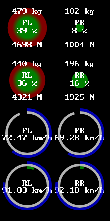
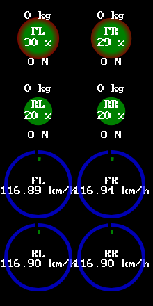
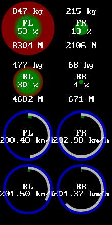
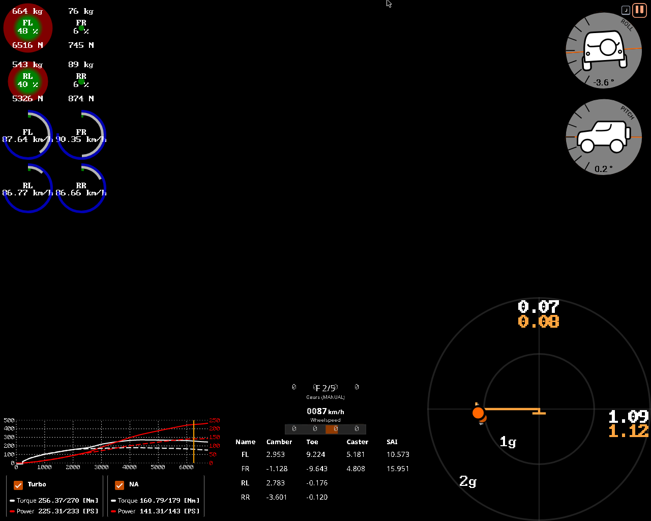
EXAMPLE: difference in lateral acceleration (cornering force) between a sport tyre (treaded, 225/45R16) and a racing (slick, 225/45R16) tyre.
NOTE1: a rear wheel drive (RWD) 2door coupe was used, on a flat tarmac skidpad, driving around a designated circular track, in a steady-state (constant acceleration), most notably using beamNG’s deterministic physics mode at 60fps, i.e. be:setPhysicsSpeedFactor(-1), as nondeterminism leads to framerate-based inaccuracies and randomness (further worsening nonlinearism), so that the simulation can be recreated on any hardware; where only the tyres were changed.
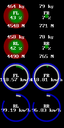
NOTE2: notably, in this steady-state test, the wheels’ (rotational) speed (frequency) (wheel revolution speed) of the slick tyres (~90km/h) is greater (faster) than the sport tyres’ (~80km/h), because they are experiencing more lateral acceleration (1.0g < 1.25g) beyond (outside) the circle (limit) of adhesion (traction), meaning they are slipping at a higher available coefficient of friction/traction, which is evident by the fact that the engine is also operating at higher revolutions per minute (RPM) (~5800RPM < ~6500RPM), but this does NOT necessarily mean that the instantaneous speed of the vehicle itself is increased - only the wheel speed is! this is exactly why one should NOT drift or slide by accident (or otherwise) in order to be fast on a racetrack.
NOTE3: notice that the vertical tyre load (weight distribution) is lesser for the outer tyres in the former (treaded) test (~477kg / ~4650N) than that of the latter (slick) one (~527kg / ~5175N). it can be further increased with even wider tyres, downforce (!) or, alternatively, with an offset wheel (not to be confused with axle track offset).

EXAMPLE: a time sensitive scenario: an oversteering f1 car in the middle of countersteering (opposite lock); where the slip angles of the rear tyres (~11 deg.) are greater than the front tyres (~6 deg.), which were generating more rotating motion overall (~8 deg.) via rear lateral acceleration (Fy), until its increasing rate was controlled and prevented by applying the opposite steering lock, improving directional stability (reducing slip) and regaining traction (grip) of the rear tyres again; where the black arrows are the direction of travel and the centreline is the yaw moment or body slip angle from the centre of mass (CoM).

typical maximum acceleration irl g-force
city car throttling ~0.3g
city car braking ~0.7g
city car cornering ~0.9g
racing car throttling ~0.9g
racing car braking ~1.3g
racing car cornering ~1.5g
f1 car throttling ~3.5g
f1 car braking ~5.5g
f1 car cornering ~6.5g
… …
maximum lateral* acceleration in beamNG g-force
burnside special stock car ~0.7g
gavril roamer roadsport ~0.8g
gavril bluebuck stock car ~1.0g
bruckell legran race ~1.1g
gavril d trackday ~1.1g
gavril barstow tracksport ~1.1g
ibishu hopper trackday ~1.2g
bruckel moonhawk track ~1.2g
gavril grand marshal trackday ~1.2g
ibishu covet turbo race ~1.2g
ibishu miramar trackday ~1.2g
etk 800 trackday ~1.2g
etk i trackday ~1.2g
soliad lansdale race ~1.3g
bruckell bastion hotlap ~1.3g
cherrier vivace tarmac rally ~1.3g
ibishu bx trackday ~1.4g
etk k gt4 ~1.4g
hirochi sunburst time attack ~1.5g
ibishu pessima (gen2) touring car ~1.6g
soliad wendover hillclimb ~1.6g
ibishu pessima (gen1) tarmac hillclimb ~1.6g
cherrier vivace hillclimb ~1.6g
civetta scintilla race ~1.8g
hirochi sbr4 tarmac hillclimb ~1.9g
civetta bolide gtr group 5 ~2.0g
… …
*: vanilla presets; steady-state acceleration, pure cornering, no braking; on a flat surface and at speeds as fast as at least 150km/h.
random maximum acceleration irl g-force
negative human threshold (constant) ~-2.5g
human sneeze ~2.5g
space shuttle throttling ~3.0g
human slap ~4.0g
ww2 aircraft dogfighting (constant) ~6.0g
positive human threshold (constant) ~10g+
human punch ~20g+
horizontal human threshold (whiplash) ~50g+
documented human limit (crash) ~200g
… …

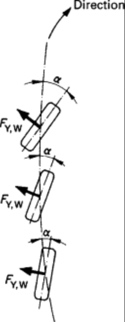
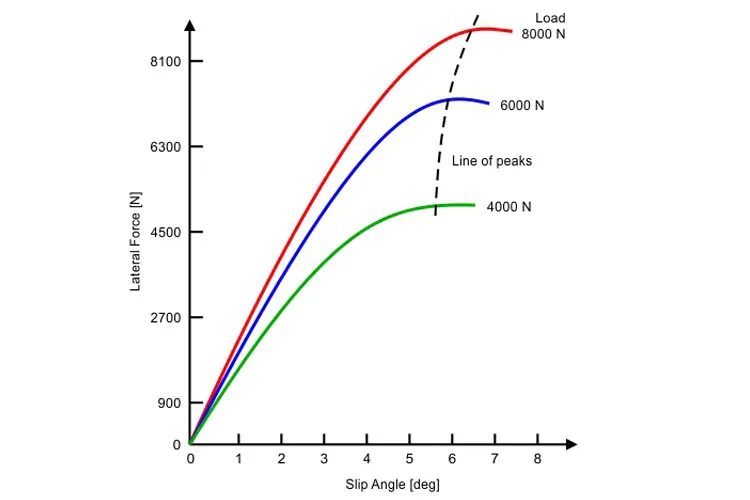
formula one bolides (in dutch, french and italian meaning a fast car) produce a peak of ~6.5g of lateral (cornering) forces at just three (3) degrees of the slip angle, thanks to the downforce producing vertical tyre load applied via the aerofoils. however, it comes at a cost: the decreased coefficient of friction (CoF) means that the vehicle gets unstable (i.e. slipping) quicker than that of production (passenger) cars, which is why they are designed to have a small steering lock (turning radius) (15 to 20 degrees) and a short steering ratio (180 to 360 degrees)[*].

[*][show]

…

the main one is the steering lock, which needs to be 21 degrees in order to get round the loews hairpin (monaco gp). normally an f1 car has a steering lock of 17 degrees.

it is possible to run a standard steering lock and still make the turn, but engineers tell me that it is around 3/10ths of a second slower, so everybody runs the extended steering range.

james allen

…

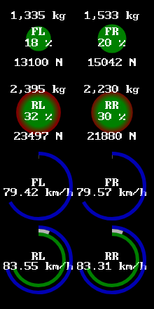
in beamNG, the civetta bolide GTR group 5 is the only car in the game capable of benefitting the most from the downforce alone. it is light (statically: ~235x2kg + ~320x2kg = ~1100kg; dynamically (300km/h): ~390x2kg + ~630x2kg = ~2000kg), which makes it possible to almost double the tyre load, effectively increasing the cornering force. however,

NOTE: the power-to-weight ratio was omitted and will be included in future tutorials.

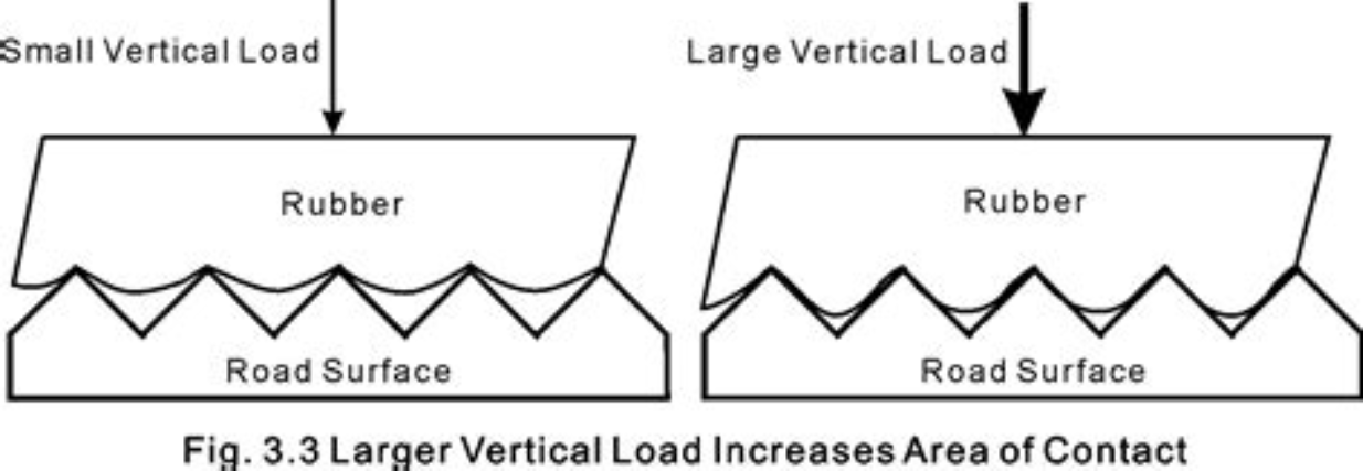
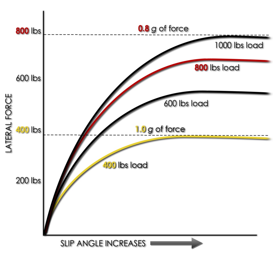
the (vertical) load sensitivity of most real tyres in their typical operating range is such that the coefficient of friction decreases as the vertical load (Fz) increases. the maximum lateral (cornering) force that can be developed does increase as the vertical tyre load increases, but at a diminishing rate.

as mentioned in the article about tyre load sensitivity,

pneumatic tyres do not behave as classical (rigid) friction theory would suggest, as they are non-rigid…

…which means that doubling (200%) the tyre weight (load) on a tyre does NOT double the amount of cornering force a tyre can generate, i.e. normal force is NOT proportional to coefficient of friction/usable traction and/or tyre weight (load) is NOT proportional to cornering force, but it DOES increase, with the peak being shifted towards larger slip angles (see fig. load3 & slipangle_6deg).

this is why lower tyre pressures or softer compounds have better traction (grip) at the cost of faster degradation and extreme sensitivity to temperature:

soft rubbers often provide better traction but also wear faster and have higher losses (of traction) when flexed, thus reducing efficiency.

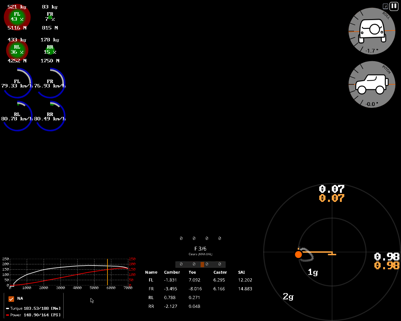
this is also why at only one (1) degree of the slip angle, the aforementioned car in the game, which also has relatively soft tyres (27:24psi or 1,8:1,6bar), is able to produce almost 2g of lateral acceleration, which is extremely sensitive to a casual driver. this also shows that lightweighting (also known as weight reduction), such as interior stripping, is important for improving vehicle handling in this case.


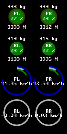
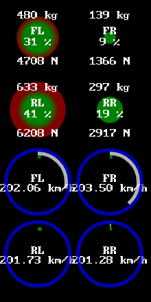
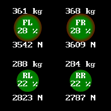
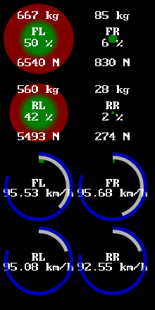
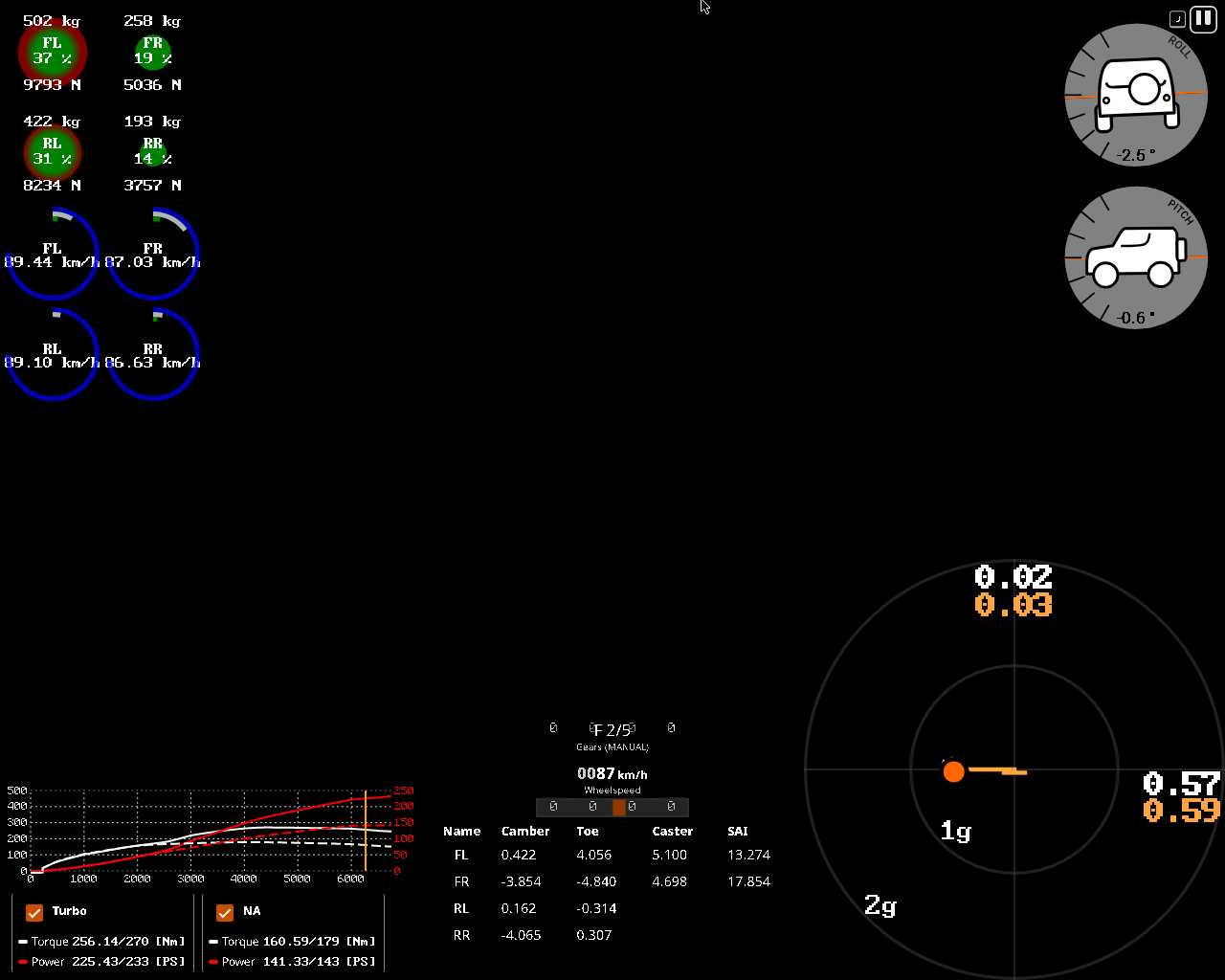
EXAMPLE: difference in lateral acceleration (cornering force) between a car without (left) and with (right) aerofoils on a front wheel drive (FWD) 4door sedan cornering to the right with sport (215/45R17) tyres.
NOTE: via the power of downward lift forces alone, a greater cornering acceleration was achieved, evident by the fact that the axles are loaded mostly evenly (35:45 vs 36:40) and require less steering input to achieve the same lateral acceleration as in the example without aero parts installed. this results in requiring more engine power at speeds over 150km/h, as well as getting used to the fact that the overall handling was changed, again, only at high speeds, making it possible to force a FWD car to oversteer like an RWD car via downforce, without any wheel alignment (more on this later).

NOTE: in beamNG, most spoilers are non-adjustable (fixed), so the angle of attack is unknown.

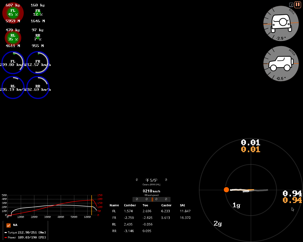
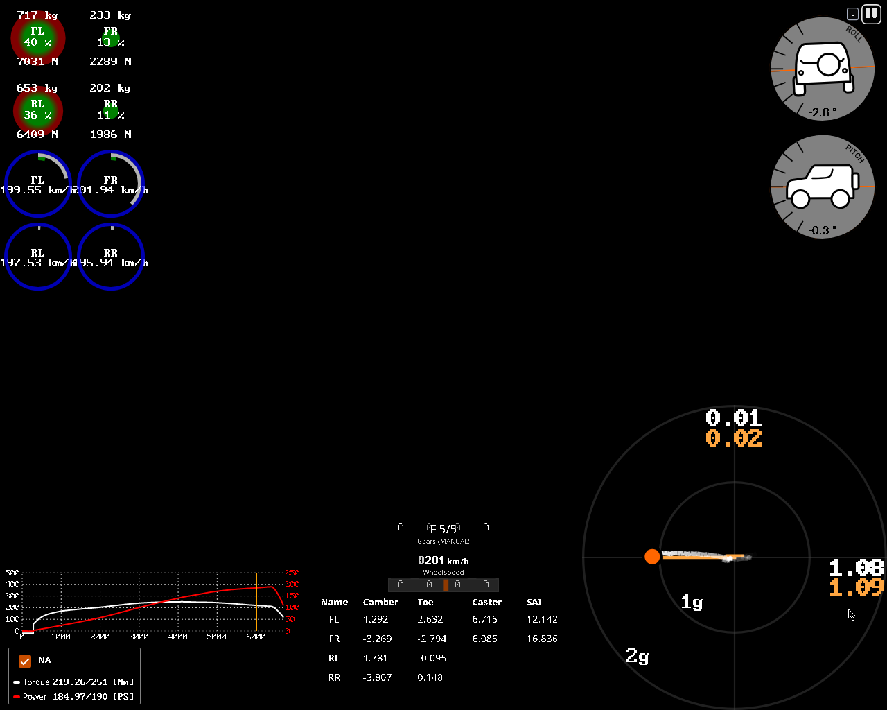
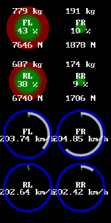
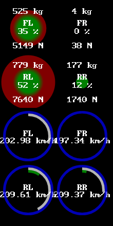
EXAMPLE: fullaero shows the effects of downforce while cornering to the right. dynamically, the best case scenario would be an equal weight and/or load transfer to the outer tyres (e.g. ~40:~40), but the aerofoil selection in beamNG is limited; splitonly shows the effects of installing only a splitter without a spoiler, where the aerodynamic drag cause the front axle to pitch downwards so much so that the RR wheel is effectively lifted off the ground, resulting in an oversteer; wingonly shows the effects of installing only a spoiler without a splitter, where the rear axle has a greater traction than the front axle, causing an understeer, which is more prevalent for RMR or rear-engined layouts; wingonly2 is ditto, except the opposite of splitonly, where the FR wheel is off the ground.
NOTE1: different cars were used! this is a TODO.
NOTE2: this goes without saying, but some of these examples are exaggerated and are not true to real life.

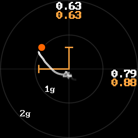
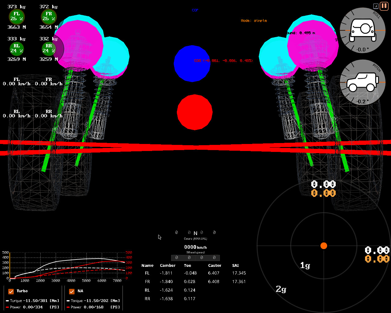
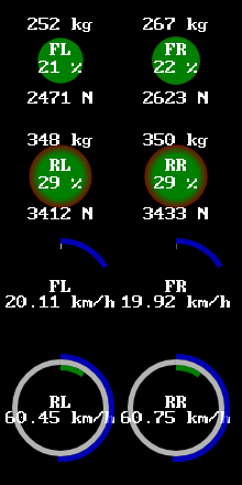
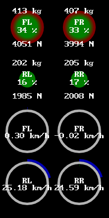
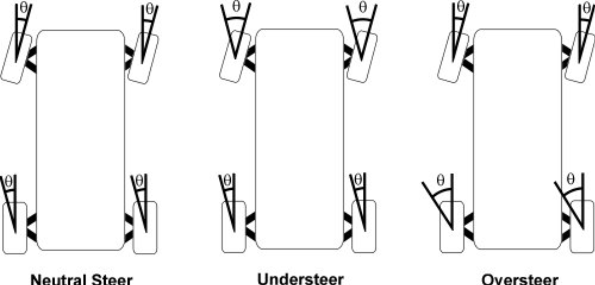
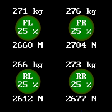
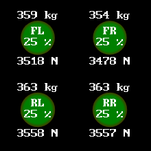
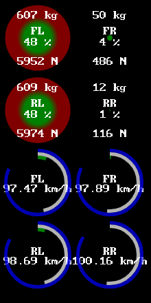
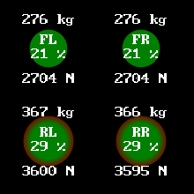
EXAMPLE: the best case scenario: a balanced handling in static and dynamic measurements, where on the left is the weight distribution in static (every wheel is carrying 1/4 or 25% of the overall sprung mass) and on the right is the weight/load transfer in a dynamic measurement (while cornering), where the outer wheels have an equal tyre load, contributing to or promoting a neutral steer (every wheel has an equal 1:1 slip angle of the front and rear axles).
list of 50%:50% cars in beamNG
ibishu hopper trackday
burnside special stock car
gavril barstow tracksport
gavril d trackday
gavril roamer roadsport
hirochi sunburst trackday
etk i trackday
etk k trackday
etk k gt4
ibishu pessima trackday
ibishu bx trackday
ibishu wigeon mantis
gavril grand marshal trackday
…

…are the only cars in beamNG with a balanced weight distribution in static and/or good load transfer / tyre sensitivity while cornering (~100km/h). every other car in the game is either slightly understeering or oversteering due to an unbalanced weight distribution (see examples below).

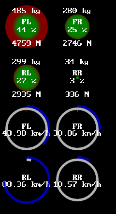
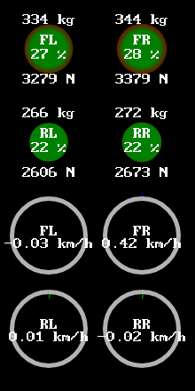
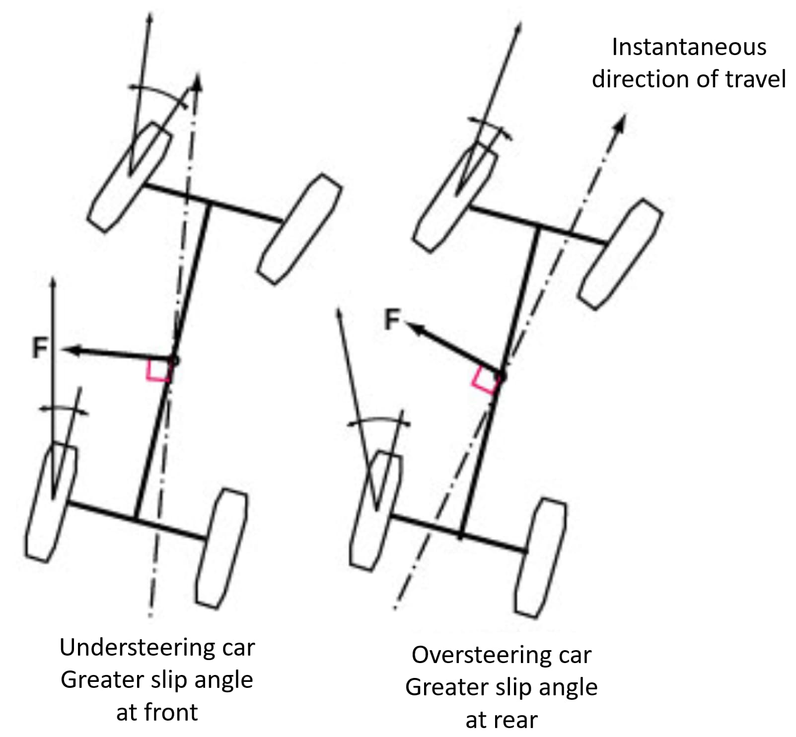
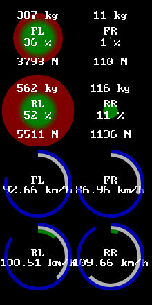
EXAMPLE: a typical front-engine front wheel drive layout (FF) and cornering behaviour; such drivetrain setups are front-heavy and are sensitive to understeering.

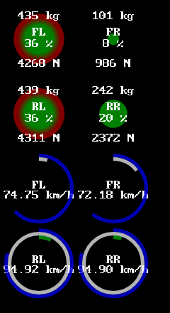
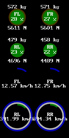
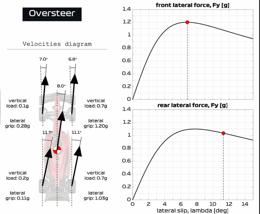
EXAMPLE: a typical middle-engine or rear-engine rear wheel drive layout (RMR) and cornering behaviour; such drivetrain setups are rear-heavy and are sensitive to oversteering.

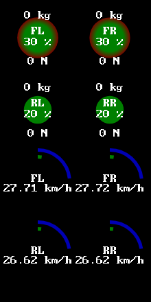
EXAMPLE: a bonus hypothetical scenario, where the earth’s gravity was doubled (2g); the weight distribution under 2g of gravity gives NO apparent benefits than under normal gravity. the tyres must put a greater effort in steering (as seen in toe angles), because twice the increased tyre load introduces slippage at lower slip angles at ANY speed, unlike what happens at high speeds with downforce.
NOTE: some players in beamMP abuse this environmental gravity to gain artificial “grip”. however, as mentioned previously, twice the tyre load does NOT equal twice the cornering force.

:left_arrow: :wheel: :counterclockwise_arrows_button:


TODO: this is literal hell. i should simplify.

traction theory (frictional forces) states that one of the main factors affecting coefficient of friction/traction are:

relative motion of tractive surfaces, where a sliding (slipping) object (one in kinetic friction) has less traction (grip) than a nonsliding object (one in static (rolling) friction).

as well as…

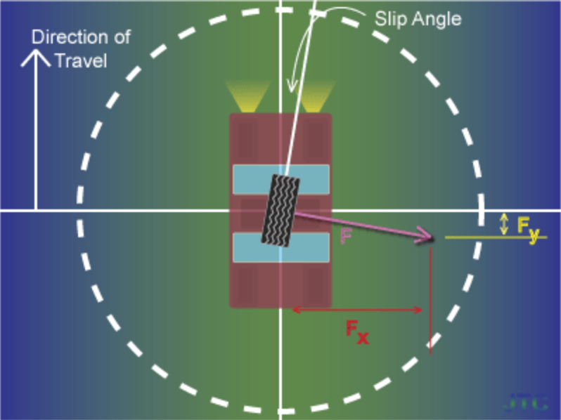
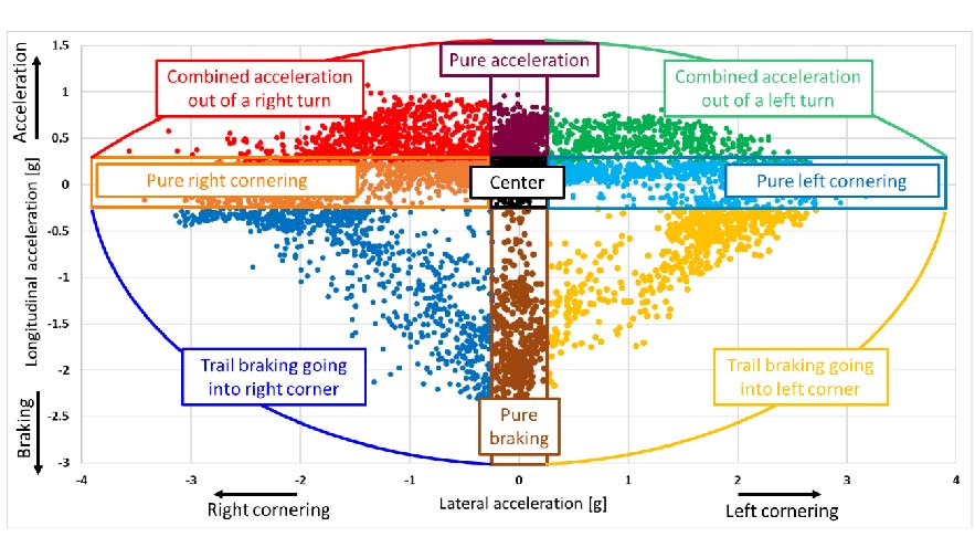
direction of traction relative to some coordinate system (traction circle), e.g. the available traction of a tyre often differs between cornering, accelerating, and braking, or all of the above combined.

moreover:

the tyre can withstand approximately the same absolute force relative to the road surface in any direction. graphically represented, a circle (or ellipse) of force magnitude represents the maximum tyre traction, and the force vector can be in any direction up to the limit of the circle without tyre slip. a tyre that can withstand 0.8g of force in braking can also withstand 0.8g of force in turning or in acceleration, or for example approximately 0.56g of cornering and 0.56g of braking simultaneously, summing to 0.8g at a 45 degree (slip) angle. once the force exceeds the limit circle, that tyre starts to slide (slip).

coulomb friction theory says that the maximum horizontal (lateral) force developed should be proportional to the vertical load on the tyre. in practice, the maximum horizontal (lateral) force (Fy) that can be generated is proportional, roughly, to the vertical load (Fz) raised to the power of somewhere between 0.7 and 0.9, typically.

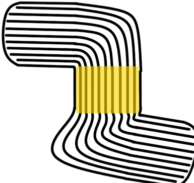
so, if the traction (adhesion) circle (static friction) is exceeded (overcome), the tyre(s) will slip (kinetic friction), as in spin faster than the other tyre(s), because kinetic friction has a lower coefficient of friction (CoF) than static friction (e.g. ice vs tarmac, steel vs rubber), which can lead to an understeer or an oversteer. this phenomenon is the same as that of a brake lockup, when the tyres are NOT in a rolling motion, but rather sliding (as if with engaged handbrake), as the dry friction generated is mainly kinetic - relative motion between two objects (tyre & ground). therefore, it is slower and more difficult to regain traction when the tyre is slipping at a full kinetic friction (>1g), than keeping a margin of some static friction (~1g), as less deceleration and slowing down is required, because the threshold of adhesion (stiction) between static and kinetic frictions would increase considerably, e.g., when controlling an understeer, it is impossible to return to the same lateral acceleration as before the understeer. remember: a tyre in a rotary motion is actually stationary (NOT moving), as the contact patch is subsequently sticking (adhering) via static friction (see previous post), unless it is slipping. this may sound absurd and difficult to understand, but it is an optical illusion, a yet another convention (social norm) that literally everyone (engineers/scientists) agreed on:

even though the wheel is in motion, the patch of the tire in contact with the ground is stationary relative to the ground, so it is static rather than kinetic friction. upon slipping, the wheel friction changes (via stiction) to kinetic friction.

thus, a slipping tyre spinning at a wheel speed of 100km/h faster than the vehicle speed of 75km/h has (roughly) the same coefficient of traction/friction as a tyre that is NOT rotating (wheel speed of 0km/h), but sliding at the velocity of the vehicle (75km/h), because the threshold (limit) of adhesion (traction) has been exceeded (overcome). basically, a locked up and a slipping tyre is easy to maintain simply by lifting the pedals and steering straight:

this is why driver training courses teach that, if a car begins to slide sideways, the driver should avoid braking and instead try to steer in the same direction as the slide. this gives the wheels a chance to regain static contact by rolling, which gives the driver some control again.

however, when describing understeer and oversteer, we use the same definition for both steady-state (linear) and nonlinear (frictional) situations, i.e. when the tyres have traction (grip) or not, or whether the tyres have reached the maximum cornering force peak at a given slip angle or not. so, “under the limit” is a linear, natural and a predictable characteristic of the tyres, whereas “over the limit” is a nonlinear, random and non-deterministic consequence (result) of oversaturation or overwhelm of the tyres, often induced by the driver’s input. for example, in motorsport, an ideal racing line is done by “touching” the apex of a corner, where if a professional driver misses the braking point - the driver will not panic and the car will simply travel a longer, suboptimally “wide” arc - all while “under the limit”, but if an inexperienced driver misses the braking point - they might try to overcorrect their error and lock up the brakes and/or steer too much so that the car understeers or oversteers - a human-induced “over the limit” scenario. this is an important difference: the distinction between a vehicle setup (configuration), e.g. wheel alignment (design); and a vehicle response (behaviour) to lateral accelerations (physics) of/at each axle. for example, production passenger cars are designed to understeer “under the limit” even when applying throttle in a corner and never reaching the “over the limit” range. it is also why newbie drivers/students in racing/driving academies/schools (HPDE) are taught to give a “margin of error” or to drive just “under the limit”, be it of speed and/or cornering force, despite the fact that the car is capable of pushing harder - obviously, it would be more difficult to learn starting from the extreme end at first; nonetheless, usually the driving instructor cars are modified and/or converted.

car and motorsport enthusiasts often use the terminology informally in magazines and blogs to describe vehicle response to steering in a variety of manoueuvres.

but driving “over the limit” is not always accidental. because of elastic hysteresis, rubber adheres (sticks) at greater coefficients of friction/traction especially when the tyres are warm - therefore, it is also a racing strategy (e.g. in circuit racing, albeit this is seldom seen in 24 hour endurance racing, where tyres’ durability is more important), where drivers deliberately corner just "over the limit” (peak) of the tyre’s maximum cornering force for the tyres to generate heat quicker in order to corner at greater lateral accelerations at the expense of the tyres’ faster wear and tear, as well as their atmospheric pressure (inflation) as a reaction to thermal-induced expansion, before promptly returning to the pit stop for a tyre swap sooner than NOT driving “over the limit”; basically, in the short-term, the traction resulted is practically the same as the traction generated when cornering “under the limit”, but in the long-term, the produced thermal exchange with the tyre pressure (inflation) itself will determine the CoF/CoT, so that such aggressive cornering only makes sense for the first laps of the race. nevertheless, such preference to “push it to the limit” is extremely situational :nerd_face: :backhand_index_pointing_up: 
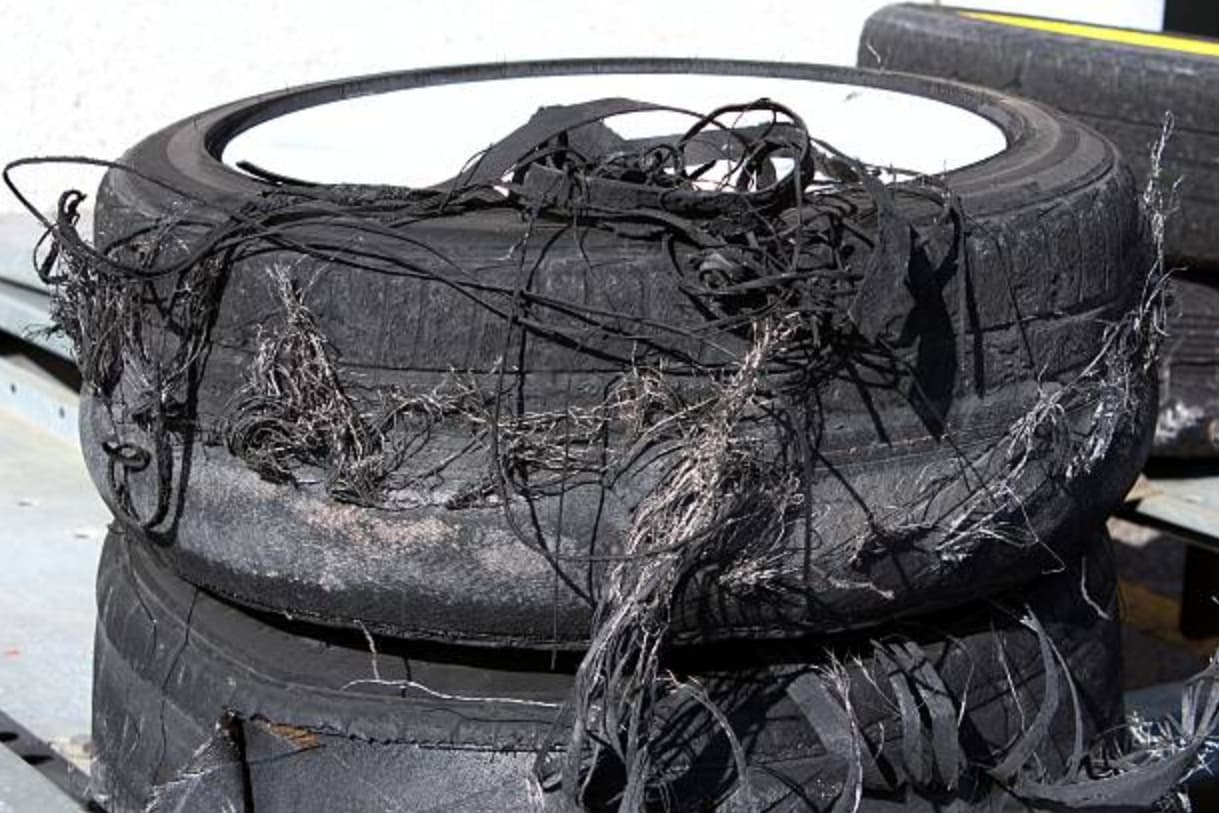
and may be inefficient (slower) on some types of racing tracks, their surfaces and conditions (see all variables above). for an extreme instance, in drifting (motorsport), a typical street treaded tyre will have its structural integrity delaminated (separation of a material’s layers) in just less than an hour (<60min) due to the excessive scrubbing and generated thermal damage (tyre’s melting point is only ~100-150*C, at which it becomes soft and liquified), rendering the traction non-existent (as well as making the tyres illegal to drive in many countries of the world), which would be suboptimal in a race having to change the tyres this often, unless special heat-resistant racing or drifting slick tyres were to be used.

in short, when your favourite sim racing youtuber/streamer/driver steers to a full lock before a tight corner - it is a deliberate technique, that is NOT “over the limit”, it is actually “under the limit”, because cars are usually designed and aligned to understeer, which is safer than oversteer.

NOTE: unlike other sim racing games (e.g. iRacing), beamNG does NOT have tyre thermal simulation by default, but it can be installed using this user created mod (which will be deprecated with the next major tyre update):

…

TODO: explain slip ratio and its relation with CoF!!!
TODO: wheel alignment is next.