VEHICLE DYNAMICS SIMPLIFIED (WIP):
SLOW INTERNET WARNING: THERE ARE PICTURES!
NO AI POLICY:
i REJECT clankers in use of my work to “train” models.
#fuckai
only autism was used in the making of this horror (it took months)…
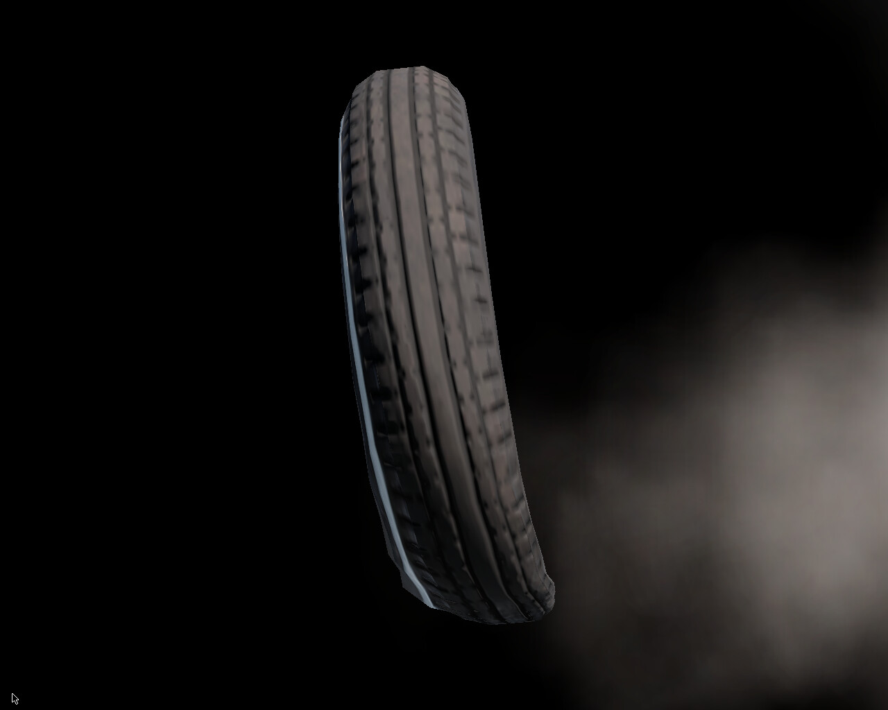
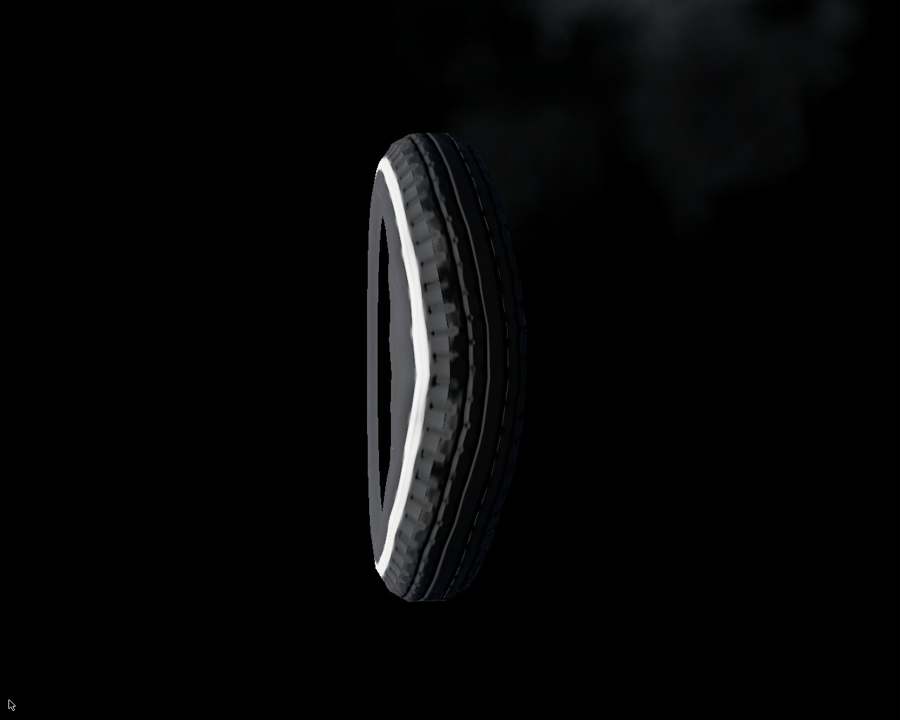
NOTE: wheel turning LEFT!
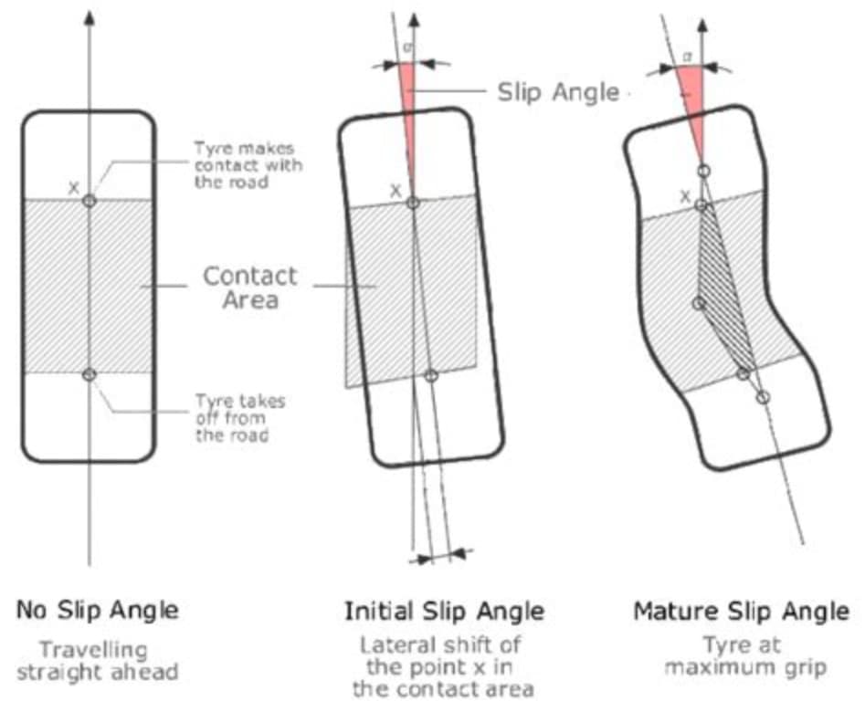
(SIDE)SLIP ANGLE
is a “shifting” angle of rolling (static) subsequent (incoming) viscoelastic contact patch deflections relative to the centreline of a tyre, i.e. the difference in degrees between where the tyres are pointing to (heading) and where they are actually travelling to (course).
no literal slippage occurs, actually. ![]()
![]()
tyre’s “sticky” (adhesive) nature, like honey, resists (stretches and relaxes) the twisting motion and static (dry) friction with the ground texture, as well as centrifugal, inertial and drag forces, and produces a reaction force - a (lateral) cornering (side) force (or stiffness, like a spring) as a result of shearing strain (deformation) and mechanical stress (generating mechanical traction (grip)), which dissipates as heat (thermal energy).
tl;dr (CLICK)
in layman’s terms, there are four (
4) rubber bands that get squishy and stretchy - two (2) in the front and two (2) in the rear. they are going in different ways, because the front tyres can only flex so much. depending on the steering geometry and/or wheel alignment, it can make you turn too little or over 9000.
in gamer’s terms, try bunnyhopping without strafing (
-mlook). every time you touch the ground for only10ms, only then you are able to turn and look with your mouse (+mlook). similarly, the tyre steers/corners as if it was lagging - it has a high ping with the ground, as if it registers an input (contact) from an australian server (stiction). moreover, ifsv_gravityis increased, you would be able to turn better (harder, faster, stronger)! this is exactly what happens to the tyres as more tyre load (e.g. downforce) is applied.
in real life, try or imagine walking or running. when you turn, you make a sharp (angled) stepping pattern with your feet. that is because it is impossible to turn smoothly in the middle of walking or running because of static friction and inertia - the current foot that is in the contact with the ground is unable to turn on its own, while the other is in the air (like the next incoming subsequent contact patches!), unless you are stationary (or a ballet dancer / figure skater) - which is what rubber does when it “sticks” (adheres) to the ground every millisecond as it appears to be “rolling”, when in fact, as far as physics are concerned, the tyre is static (stationary), i.e. the contact patch is quite literally “walking”. it is only “temporarily” in motion, as it overcomes static friction. so, you are NOT moving RELATIVE to the ground, UNLESS you are on ice or slipping, which is no longer static - it is kinetic friction!
…
slip angle varies with slip ratio (longitudinal rolling percentage), (vertical) tyre load, aerodynamic forces (downforce, ground effect, drag coefficient, centre of pressure), weight and/or load transfer (centre of mass, centre of gravity), atmospheric pressure (pneumatic inflation), engine power and engine (machine) torque, speed (torque, horsepower, angular acceleration, angular velocity, rotational inertia, etc.), unsprung (suspension) mass and sprung (gross) mass, roll centre, weight distribution, body roll, automotive electronics (ABS, TCS, ESC, etc.), suspension geometry (height or clearance, anti-dive and anti-squat, anti-roll or anti-sway bars), steering geometry (ackermann, power steering), wheel alignment (camber and centripetal forces, castor, toe), tyre tread (pattern) (racing slick, stiction, tractive (traction) force, indentation hardness, rolling resistance) and surface conditions (static and kinetic (dry) friction and their coefficients, road slipperiness), et cetera.
NOTE: slip angle is NOT to be confused with slip ratio - the forward (longitudinal) forces as a percentage of the velocity of the vehicle relative to the observed (perceived) angular velocity (free-rolling speed) of the tyre, i.e. apparent (evidental) slipping (sliding) or “locking” due to excessive acceleration (throttle) and/or deceleration (braking). however, it is just as important, e.g. in trailbraking and drifting.
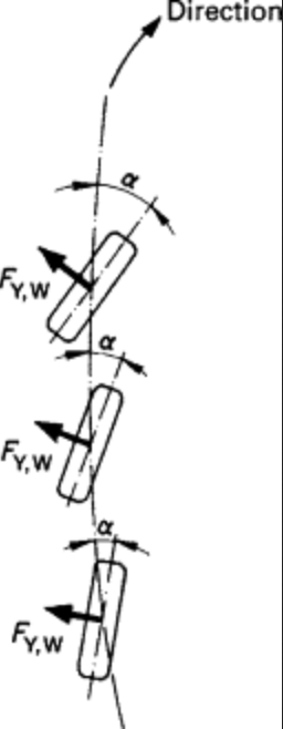
when steered, the front tyres generate a “twisting” yaw moment around the vehicle’s centre of gravity (CoG), which results in additional slip angles on the rear tyres, supporting (combining with) the vehicle’s turning (inertial) motion - a centripetal force.
the assymetric slip angles of the front AND rear tyres will determine the behaviour of the vehicle as it is turning.
…
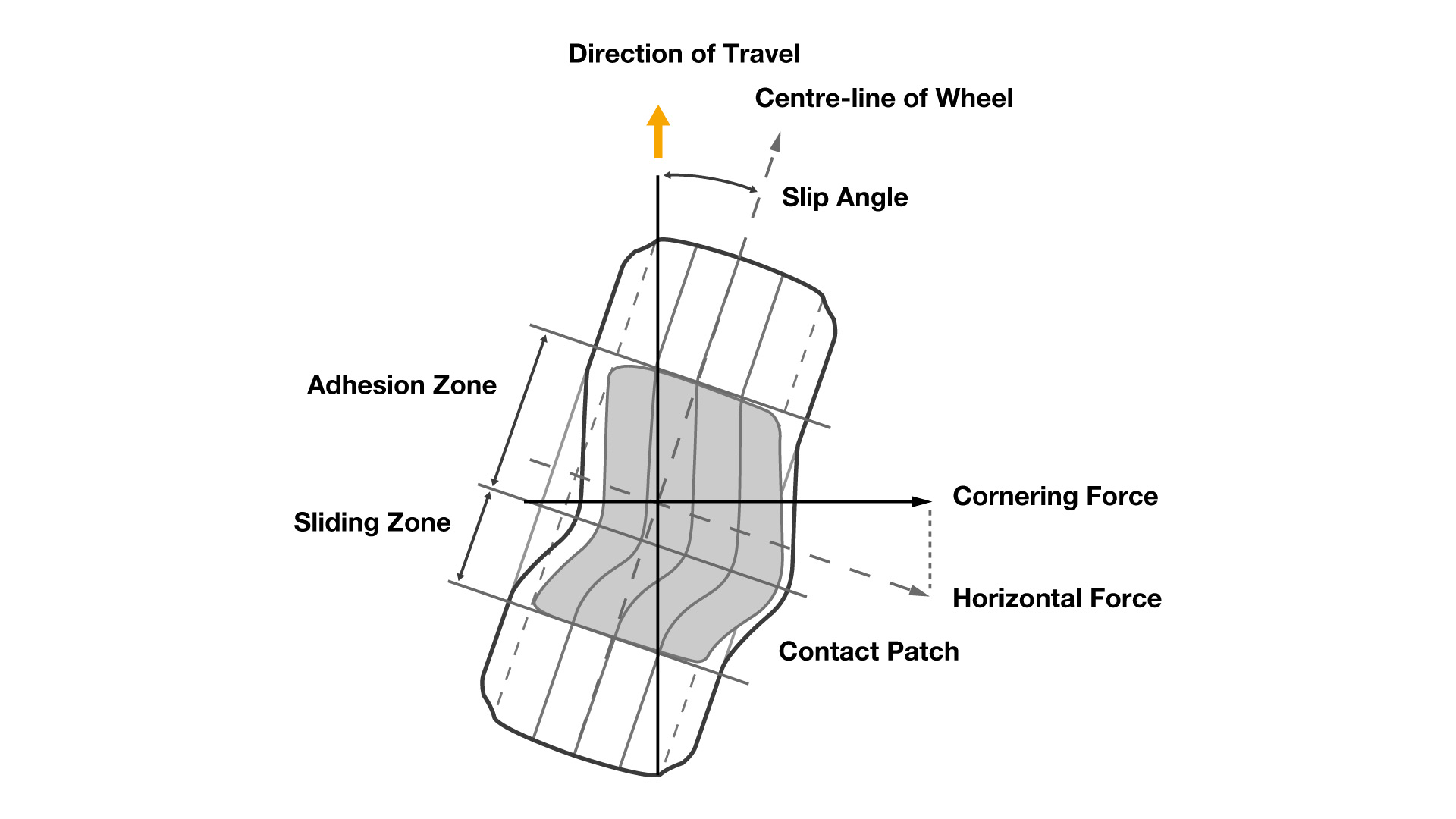
NOTE1: wheel turning RIGHT!
NOTE2: the cornering force is created perpendicular (90 deg.) to the direction of travel, i.e. towards the steering, opposite to the centrifugal and/or inertial force.
EXAMPLE: in beamNG; wheel turning RIGHT! viewed from directly behind and below the front left wheel.
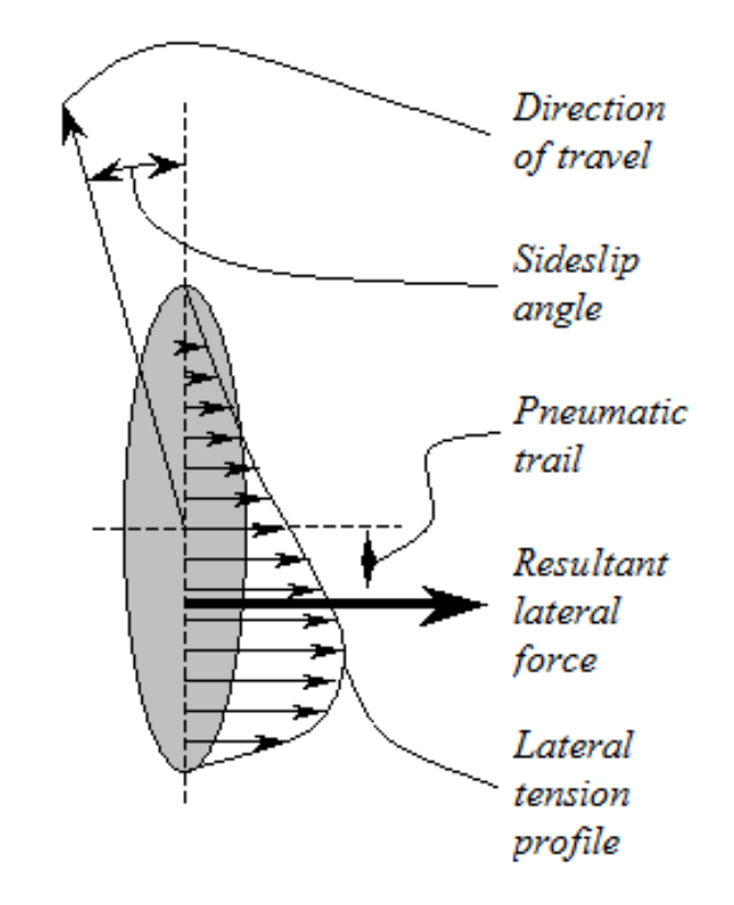
the cornering (lateral) force increases to a maximum (peak/limit), until the adhesive/stick area/zone of the contact patch is exceeded/overcome by the slip/slide area/zone (slippage/creepage), as it begins to decrease (fall/“cliff”) again. its increasing rate is described by the relaxation length and the distance of the pneumatic trail, which create a self aligning torque (moment) at the trailing edge (behind) of the contact patch, as it returns to its original (linear) shape (outside of the contact patch, repeating the cycle).
the cornering force is measured in newtons (N) or pounds of force (lbf).
you can test how much of this cornering (lateral) force your vehicle is able to withstand at a given slip angle by viewing/observing it dynamically via a GG diagram (accelerometer) and/or experimentation to determine at which limit (peak) the frictional (kinetic) slip and loss of traction (grip) does develop (saturate) at each axle.
…
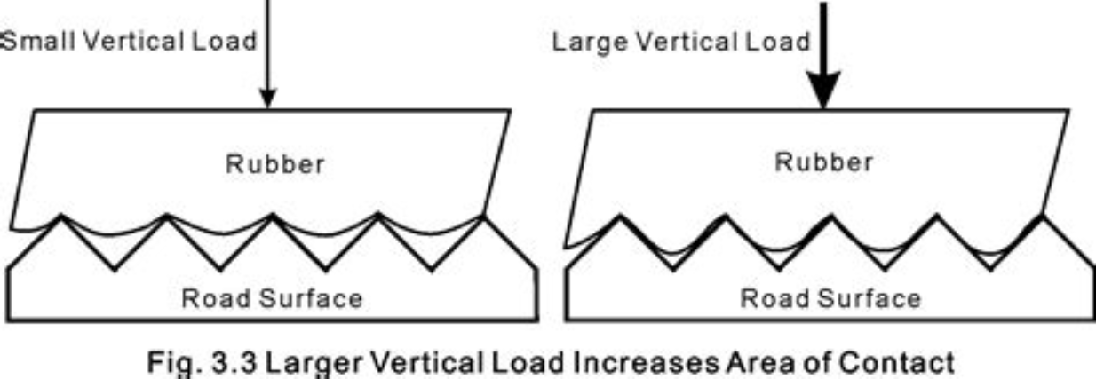
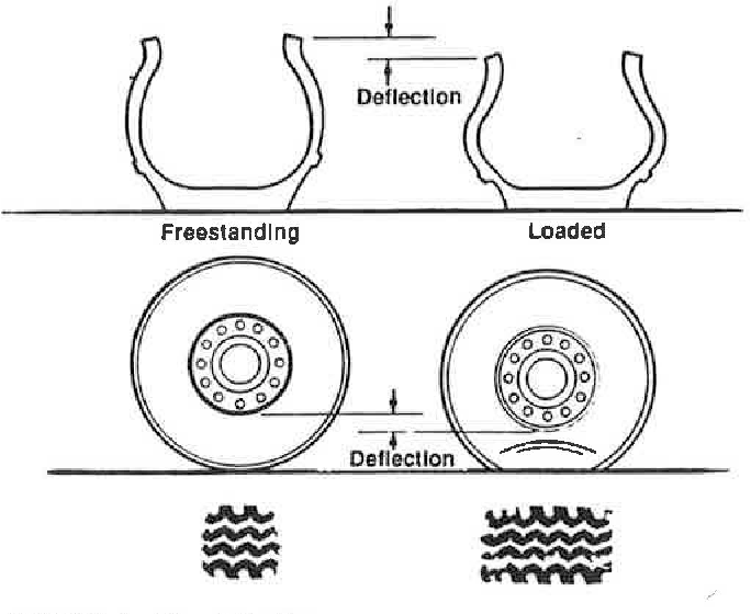
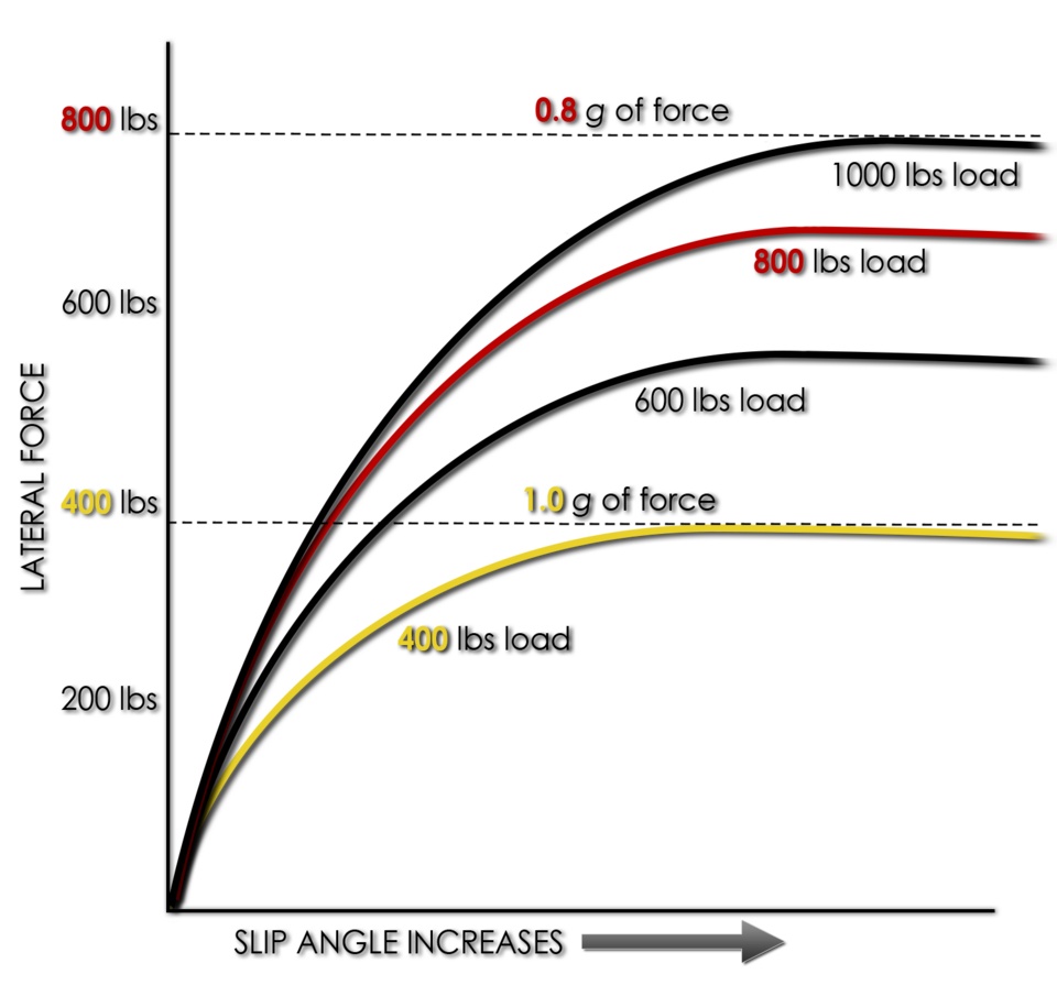
EXAMPLE: to achieve a larger contact patch and better traction (grip), a greater vertical tyre load must be applied, which would decrease coefficient of friction, but increase cornering force, but at a diminishing (decreasing) rate. however, it is NOT necessary to add more to the overall sprung weight or change (deflate) the tyre pressure! it is also possible to change the shape of the body (bodykit) and install aerofoils: a splitter (air dam), bonnet (hood) scoop, roof scoop, spoiler or wing and a diffuser, etc., that would create a greater downwards lift force - downforce (the same principle as the horizontal stabiliser of a plane), which is also proportional to the aerodynamic drag (air resistance), meaning that it increases with the square of the car’s speed (velocity) and requires a certain minimum speed in order to produce a significant effect, so that the excessive use of which may hinder (worsen) acceleration, top speed and the overall handling of the vehicle! it is always a compromise to find the perfect L/D (lift to drag ratio) balance, spring (ride) height and the angle of attack of the aerofoils for a given racetrack (as well as its inclinations!) and average speeds. for examples, see next posts.
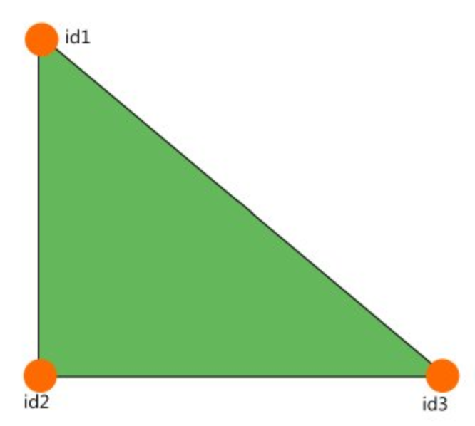
NOTE: it is worth noting that, in beamNG, fluid dynamics (incl. tribology) are simplified - the drag coefficient is predetermined (baked) into each and every coltris (triangle) of the jbeam:
the aero system in beamNG works by calculating drag on all triangles based purely on the speed of the airflow, the surface area and drag properties of the triangles. the drag and lift forces are then applied on the adjacent nodes. triangles are NOT affected by other triangles, meaning that triangle in the back of your vehicle will still create the full drag.
because of this, you (the mod author) might need to fine tune the drag coefficient of your various components based on how exposed to airflow they are. this also lets you add surfaces to simulate ground effect, or fine tune the lift distribution on your vehicle.
…